
In general, available interactive functionality depends on the chosen projection and the type of data being viewed. In any mode, mouse wheel can be used to zoom in and out.
WIRED 4 views are displayed in the right panel of Jas3, either as tabbed panes or as internal frames (use "View" - "Windows Style" menu to switch between these two modes).In the "Internal Frames" mode, several WIRED plots can be viewed at a time, but only one of them can be selected. Information shown in the active control panel reflects the state of the selected view; any actions initiated using control panels or tools affect the selected view and its clones.
Every view is associated with a model that contains current parameters of that view: visibility settings, selected objects, tools and control panel settings, applied cuts. New views can be opened either by selecting "File" - "New" - "Wired4 View" menu item (default model settings will be used) or by selecting "New View" from the popup menu of an existing view (initial model settings will be copied from that view).
Views can also be cloned by selecting "New View" from the popup menu - the newly created view will share the model with an existing view, so any changes to visibility settings, object selection, or cuts will be applied to all clones simultaneously. This is useful for looking at the same set of objects from several different angles, for example.
Control panels are displayed in the left tabbed pane of the application window. Only one control panel is visible at any given time. Panels can be selected either by clicking their tabs or by typing keyboard shortcuts while the cursor is over a WIRED plot: V - visibility tree panel, I - selected instance information panel, C - cuts panel. Clicking a tab of an already selected control panel activates one of the tools considered native by that panel (the one used most recently). Take a look at the buttons at the top of each control panel to see what tool are native for that panel.
![]() Visibility Tree Panel
Visibility Tree Panel
The panel displays type and instance trees for the currently loaded event, and allows the user to control visibility of objects in WIRED plots. There are two checkboxes associated with every non-leaf node in the tree. Unchecking the left one hides the whole branch below that node; unchecking the right box hides the node itself. Controls at the bottom of the panel allow hiding all types or instances below a certain level in the tree.
Highlighted nodes in the tree denote currently selected instances (if there is a selected instance in a collapsed branch below a certain node, the node name will be displayed in bold type). Instances can be selected either by using one of the picking tools, or by selecting nodes in the tree - clicking a node makes it the only selected node unless it's already the only selected node; in the latter case, it deselects it. Control-click toggles selection state of a node. Typing "D" while the cursor is over a WIRED plot deselects all instances on that plot.
![]() Information Panel
Information Panel
The panel displays a list of currently selected objects. If there is exactly one selected object, its attributes are shown in the table at the bottom of the panel.
"Options..." button near the selected objects table can be used to instruct picking tools to select objects from specific layers or types.
"Options..." button near the "Attributes of selected object" table allows the user to choose what attribute categories should be displayed.
![]() Cuts Panel
Cuts Panel
Cuts allow the user to interactively hide or display objects based on values of their attributes.
To enable cuts on a WIRED plot, check the "Apply" box. Cuts can be inverted by putting a checkmark into the "Invert" box. Exactly what the inversion means is controlled by the "Pass Through" checkbox. If the box is checked, objects that do not have attributes used by cuts remain visible whether or not the cut set is inverted. If the box is not checked, inverting cuts hides all objects that would be visible if the cuts were not inverted.
Cuts table lists all loaded cuts, but only cuts with a checkmark in the "Apply" column are applied to the currently selected plot. New cuts can be created and existing cuts can be deleted using the "Actions..." button.
Types panel can be used to select object types to be affected by the cut.
Conditions table allows switching on or off and inverting individual conditions that constitute the cut. Each condition corresponds to a name of plottable object attribute - numeric, boolean, or a string. The range of acceptable values for each condition can be adjusted by clicking its "Accept if" cell. Resetting a condition makes it accept all objects (or reject all objects if the condition is inverted).
By enabling, disabling, and inverting individual conditions, cuts, and cut sets associated with plots virtually any desired selection logics can be implemented. Note that conditions are owned by cuts - changing parameters of a condition does not affect identically named conditions in other cuts. However, cuts are shared by all plots, though they can be individually enabled, disabled, or inverted on every plot. Therefore, changing parameters of a cut will affect all plots where that cut is enabled.
Of the tools described below only one can be active at a time. The active tool is indicated by the corresponding button being depressed, the corresponding menu item in the popup menu being flagged, the corresponding control panel being shown. Any mouse interaction started may be interrupted by pressing the Esc key. Tools can be selected using toolbars or keyboard shortcuts. Clicking a button of an already active tool selects the control panel native for that tool.
![]() Scaling
Scaling
Scaling will allow you to enlarge or shrink the picture you are currently seeing. You can also zoom into a region on the screen. When you select the Scaling mode, the control panel will show you a choice of three sub-modes in its Selection box:
![]() Translation
Translation
Translation allows you to move the picture anywhere inside the view. Translation (apart from incurred by any of the scaling modes) will only work in direct mode. The control panel will give you no other choice.
When you drag the left-mouse button the picture underneath will follow until you release the mouse button. If you click, the clicked point will be centered. If you alt-click the center will move to the clicked point.
Translations like these will only have an affect on the currently viewed angle. So, if you click on a calorimeter cluster, the cluster will move to the center of the screen, however if you go on to rotate the cluster, you will find that the model is not centered along the screen's Z-axis. In fact what will most likely happen is that the model will float out of the viewable area while you rotate. To select a proper rotation point a 3D translation mode will be added in the near future.
![]() Rotation
Rotation
The rotation modes are both immediate. From the Selection box you may choose between:
![]() Picking
Picking
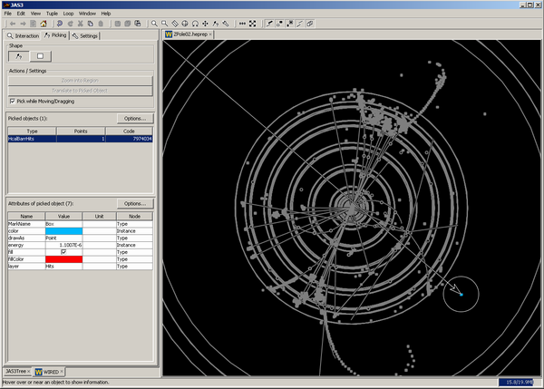
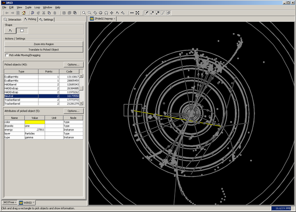
Picking allows the user to show information attached to the objects shown in the view. This attributes can be physics values or other relevant information. When you select the picking mode the control panel will allow you to select from different sub-modes:


The control panel will show a table of picked objects, which update as you change your pick of the view. If only a single object is picked, its attributes will show in the attributes table. If multiple objects are picked, then you can select one object from the picked table to show its attributes. Doing so will cause the view to only highlight that single picked object.
The Options... button in the Picked objects table allows you to restrict the picking to certain layers and to certain HepRepTypes. The layers are shown in a list, with a checkbox if this layer is used in the picking. The HepRepTypes are shown in a tree, where checkboxes mark if types are used in picking.
The Options... button in the Attributes of picked object table allow you to limit the display of attributes to certain categories. The categories are shown in a list, with a checkbox if attributes of a category are shown.
The following shortcuts can be used while the cursor is over a WIRED view:
Selecting control panel:
Selecting tools:
Pressing any tool selection key while holding the space bar selects the tool temporarily - once the key is released, the previously selected tool will become active again.
Creating new views:
Direct actions will result in an immediate change.
![]() Reset
Reset
Puts the view back into its original state of the projection.
![]() Fit to Window
Fit to Window
Fit to Window is a direct action. It will measure the bounding box of the event/geometry in its currently visible state and will Scale and Translate to fit it within the boundaries of the window. The Scaling is uniform. The Translation will center the result.